
THE GREAT SUCKING SOUND IN ENGINEERING • Part 2 of 4
Teaching my job to my replacement.

THE GREAT SUCKING SOUND IN ENGINEERING • Part 2 of 4
Teaching my job to my replacement.
The Art of Vibration and Stress of Vanes
Herbert Roberts, PE
A Metal Flag on a Stick
If you want to understand why formalizing engineering methodology into cookbook procedures was never as simple as executives believed, consider the variable vane. It is, by the standards of gas turbine design, a minor part. Not a turbine disk spinning at tens of thousands of RPM under enormous centrifugal loads. Not a combustor liner enduring temperatures that push the limits of superalloy metallurgy. A variable vane is, in its simplest description, a metal flag on a stick—a thin, flat airfoil region making up the flag, and a round stem roughly three to five inches long making up the flagpole.
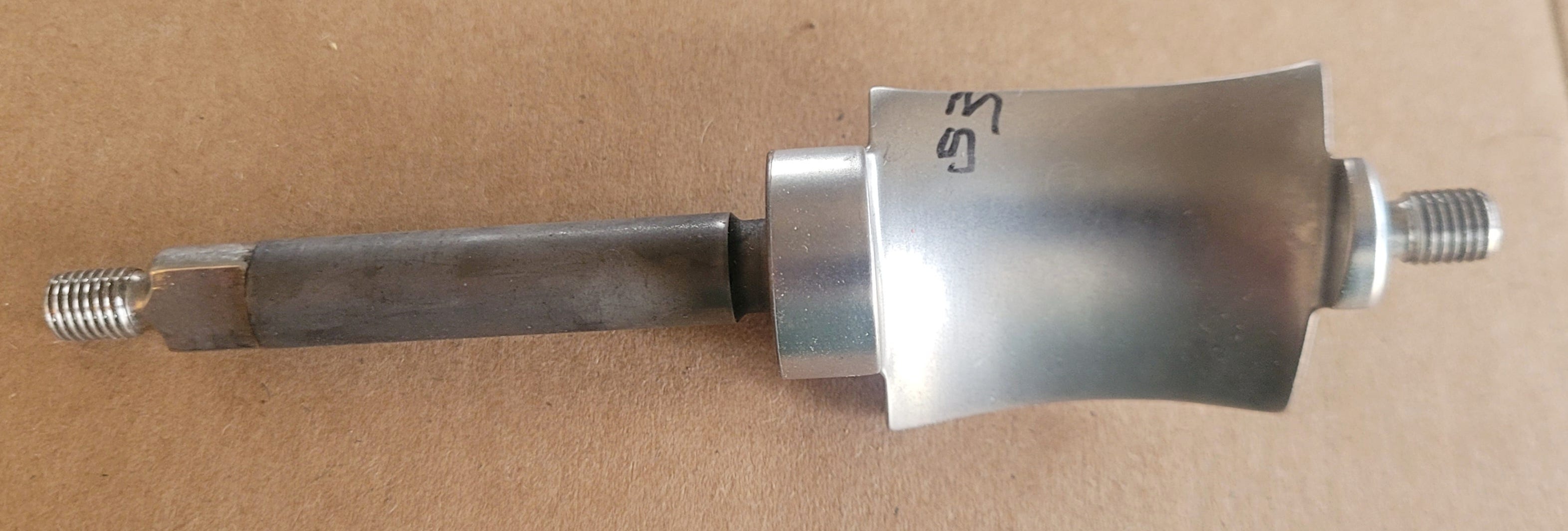
A variable vane. Photo: Herbert Roberts ©2026
It is also one of the most analytically deceptive components in the entire engine. The art required to predict its vibration response and structural stress reveals everything that rules-based documentation could not capture—and everything that was lost when the work was handed to engineers who had never seen the part fail.
Why the Vane Moves
Variable vanes exist because a gas turbine must change its operational thrust as the pilot advances or declines the throttle. The compressor section of the engine ingests air and compresses it through a series of stages, each containing a row of rotating blades and a row of stationary vanes. In a fixed-geometry compressor, the angle at which air meets each stage is optimized for a narrow range of operating conditions. Variable vanes solve this by rotating about the stem’s centerline axis to redirect the attached airfoils angle of attack which changes airflow volume as conditions change, maintaining aerodynamic efficiency of the engine across the full throttle range.
The mechanical system that accomplishes this is straightforward in concept and punishing in its analytical implications. Each vane’s stem passes through a set of bushings in the compressor case. At the outer end of the stem, an arm is attached. All the arms in a given stage—typically thirty to forty vanes—connect to a unison ring, which is itself is connected to a hydraulic actuator. When the actuator moves the ring, the ring slides around the circumference of the compressor case, and every arm rotates its vane simultaneously changing the airfoil angle.
The critical implication of this design is that the variable vane is not rigidly held in place. It cannot be. The vane must rotate tens of thousands of times over its operational life, which means its connection to the surrounding structure—through the bushing, the arm, and the unison ring—must permit motion. The part lives in a mechanical environment defined by controlled looseness. And that controlled looseness is where the art begins.
The Grounding Problem
In a finite element analysis model that predicts a component’s vibratory response to operating conditions, the single most consequential set of assumptions involves how the part is grounded—that is, how the model represents the component’s connection to the surrounding structure. For a turbine disk bolted to a shaft, the grounding is relatively well-defined: the bolt circle constrains the disk, and the boundary conditions in the finite element analysis (FEA) structural model can be specified with reasonable confidence. For a variable vane, the grounding is anything but well-defined.
Consider what determines how tightly or loosely a single variable vane is held in place at any given moment. The bushing that supports the stem may be manufactured to tight tolerances by one supplier and looser tolerances by another. The bushing wears over time, which means the fit changes with the age of the part. The level of lubrication at the stem-to-bushing interface varies with maintenance cycles and operating history. The local air temperature affects the thermal expansion of the stem relative to the bushing, altering the clearance. The current throttle setting determines the aerodynamic loading on the airfoil, which changes the contact forces at the stem. And all of these conditions apply simultaneously to each of the thirty to forty vanes in the stage, none of which are in precisely the same mechanical state at any given instant.
The grounding of the FEA model—the boundary conditions that the analyst must define before the solver can run—must somehow represent this reality. The analyst faces a choice: model the connection as overly tight, which will overpredict the vane’s natural frequencies and underpredict certain deflection modes; model it as just loose enough, which requires knowing what “just loose enough” means for a specific combination of manufacturer, age, temperature, and throttle setting; or model it as very loose, which will capture certain failure modes but may overpredict vibration amplitudes. Each choice produces a different set of results, and the range between them is not a narrow band of engineering uncertainty. It is a wide spectrum of plausible outcomes, each with different implications for the predicted operational life of the part.
Thirty Vanes, Thirty Realities
The traditional approach to variable vane analysis made a simplifying assumption that was both necessary and, for many years, adequate: if you analyzed one vane, you analyzed them all. Because every vane in a stage has the same nominal geometry, the same material, and the same operating environment, the structural response of one vane was assumed to be identical to every other vane in the set. This assumption reduced an intractable problem—modeling thirty to forty mechanically coupled, variably constrained components under transient loading—to a manageable one.
Under the old hand-calculation methods, this simplification worked. The conservatism built into the material properties, the stress concentration factors, and the boundary condition approximations provided enough margin to absorb the reality that no two vanes in a set behaved identically. The analysis was “wrong” in a way that protected the design from the variability it did not model.
As FEA models replaced hand calculations, the analysis became more accurate for a single idealized vane but no better at representing the set. The model captured stress gradients across the airfoil-to-stem transition with precision that Peterson’s charts never could. It resolved vibratory mode shapes that hand methods approximated crudely. But the boundary conditions—the grounding—still represented a single assumed state. The model knew exactly how one hypothetical vane would vibrate under one hypothetical set of constraints. It said nothing about the thirty-nine other vanes whose bushings were slightly more worn, whose lubrication was slightly different, whose thermal state reflected a position on the case that ran a few degrees hotter or cooler.
The result was a new category of field issues. High-cycle fatigue failures appeared in vanes that the analysis had cleared. Not because the FEA model was wrong about the stress in the airfoil, but because the vibratory response of the vane was governed by grounding conditions the model never evaluated. Proximity effects—aerodynamic excitations driven by the interaction between adjacent vanes, between vanes and rotating blades, between the unison ring and the case—produced forcing functions that a single-vane model could not see. The old methods had survived these effects through brute-force conservatism. The new methods had no such cushion.
What the Cookbook Cannot Contain
This is the problem that the documentation directive could never solve. An experienced structural engineer analyzing a variable vane did not simply follow steps. The engineer made judgment calls at every boundary condition—calls informed by years of watching hardware come back from engine tests, by conversations with the manufacturing engineers who built the bushings, by knowledge of which suppliers held tighter tolerances, by awareness of how the unison ring behaved after ten thousand cycles versus one thousand.
That judgment could not be written into a procedure. You cannot document a sentence like “for this vane configuration, use a grounding stiffness between X and Y, biased toward the loose end if the bushing supplier is Company A and toward the tight end if the supplier is Company B, adjusted for thermal growth at cruise versus takeoff, and validated against the last three engine test campaigns.” That sentence is not a step in a recipe. It is a paragraph of calibrated engineering judgment that took a decade to develop and requires continuous access to manufacturing and test data to maintain.
Beyond the grounding question, the documentation effort faced a second structural limitation: the interaction between analytical conservatism and modeling fidelity was never explicitly understood, which meant it could not be deliberately managed during the transition to new tools. The old methods worked not because they were accurate but because their inaccuracies were systematically biased toward safety. When the new tools removed those biases in pursuit of precision, no one catalogued what had been lost. The safety margin did not appear in any spreadsheet. It disappeared silently, and the documentation captured neither its existence nor its absence.
A Minor Part
Everything described above applies to a variable vane—a component that, in the hierarchy of gas turbine structural design, ranks as minor. It is not the part that keeps the engine on the wing. It is not the part whose failure produces an uncontained event. It is a metal flag on a stick, one of thirty or forty in a row, doing the quiet work of redirecting airflow so the compressor can function across the throttle range.
And yet, predicting its structural life requires an engineer to navigate a landscape of variable boundary conditions, manufacturer-dependent tolerances, age-dependent wear, temperature-dependent clearances, and proximity-driven excitations that no single FEA model can fully capture. The art of that prediction—the judgment that transforms a wide spectrum of plausible results into a defensible life estimate—is precisely what the documentation directive asked engineers to write down in a Word document.
The major and critical parts—the disks, the cases, the high-pressure turbine components—are exponentially more complex. If the art of analyzing a minor part could not be formalized into a transferable procedure, what chance did the rest of the engine have?
Quarterly-focused corporate leadership cut costs and built analysis-heavy systems, but stopped producing engineers — the people who carry decades of hard-earned judgment from watching hardware succeed and fail.
The shift to FEA tools discarded the conservative biases of hand-calculation methods without replacing them. Since no one truly understood what those biases had protected against, the result wasn’t just job losses — it was a massive drain of accumulated engineering value.
Thank you for following me on this journey. I would really like to hear about your experiences good and bad. Please leave a comment, especially if you are outside the US or work in a different engineering field.
© 2026 Herbert Roberts, PE • Engineering Mindset Blog • engineeringmindsetblog.com
Herbert Roberts is a Licensed Professional Engineer based in Southwest Ohio with 32 years of aerospace R&D experience and 62 patents. His forensic engineering practice translates technical failures into language the rest of the world can act on. THE BIG WHY publishes monthly. Subscribe to the Inventor's Mind Blog at inventorsmindblog.com for new posts twice weekly.